When I started on the construction of my model railway of Box
station on the Great Western mainline
between London and Bristol back
in
1992, the complexity of an up and down mainline and numerous
sidings and
a fiddle yard behind the backdrop was going to need some serious
thought as to how to
control the running of trains. It had to be by cab
control and two controllers to run up and down main
lines and needed to
be inter-connected to allow for shunting. In addition to this a third controller would
be needed to carry out train movements on the Bath
Stone Firms sidings adjacent to the up main line
and this would need to
be inter-connected to the up main line controller for smooth running.
This controller would also control the fiddle yard for train movements
independent of the other two
controllers and yet be able to be linked
to
them for trains to be able exit the fiddle yard on to the main
lines. This
meant numerous isolated sections of track to control the
trains by means of double pole double
throw centre off switches.
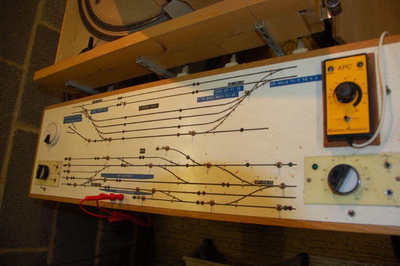
One
pole to connect either controller and the second bank to operate the
LED's to indicate on the control
panel which controller was powering
that section of track. The photograph below shows the control panel
with
the section switches and stud contacts for point operation and the
three
controllers. It is never a good
idea to put the power transformers in
the control panel because of the 240 volt supply, so these are in their
own dedicated box close to the power point and the 12 volt DC and 18
Volt AC are connected to the control
panel via 5 pin DIN plug
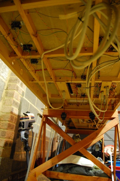
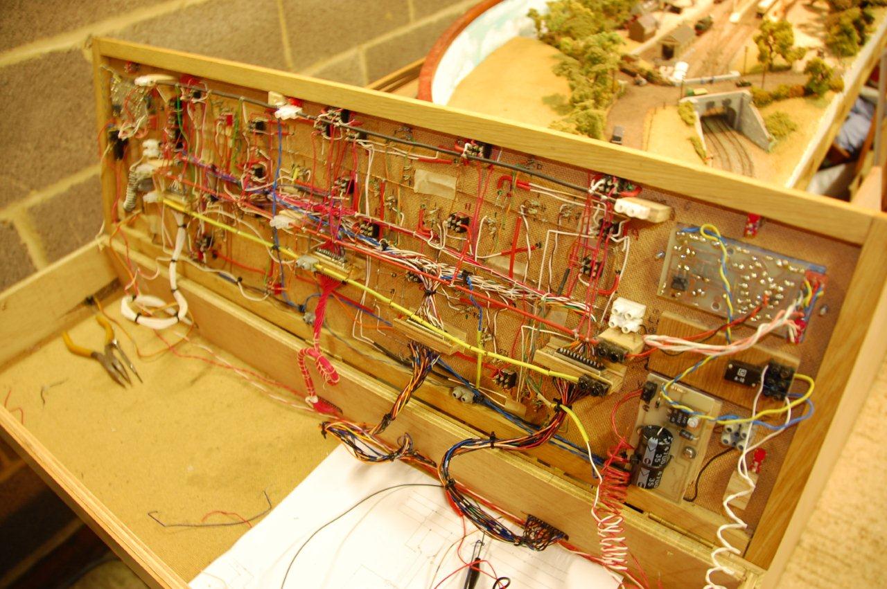
All of the wiring to make everything operate is on the
underside of the control panel lid which is hinged to allow access. The
wiring of the layout does not end there because it all has to be
connected to the track below the base boards. The base boards are two
sections each six feet long and 27
inches wide and supported on 25mm x 75mm framework for rigidity. They
also need to be connected by jumper leads to separate them for
transportation as does the control panel. To this end 32 pin computer
leads were used. This saved a lot of soldering. There are five such
outlets from the control panel to the base boards. The underside of the
base boards with its positive and negative leads to each section of
track, the point motors and polarity switching of the live frogs is
just
as much a nightmare as the control panel.
Before I undertook any of the wiring I drew up a wiring diagram
of the whole lay out to make life easier for myself in the event of a
power failure to any part of the track. This in itself was a lot of work
and comprises four double sheets of A3 paper. Two sheets glued together
horizontally. One sheet for each half of the base boards. One double
sheet for track wiring and another for point wiring and live frog
switching of polarity. These are mounted on a sheet of ply wood and attached to a wall
adjacent to the lay out. Without doubt the best thing I ever did for
this layout. It has occurred to me whilst writing this that for years I have
been driving the track and not the train and that is not prototypical.
The
Modernisation revolution : Go DIGITAL COMMAND CONTROL. (DCC)
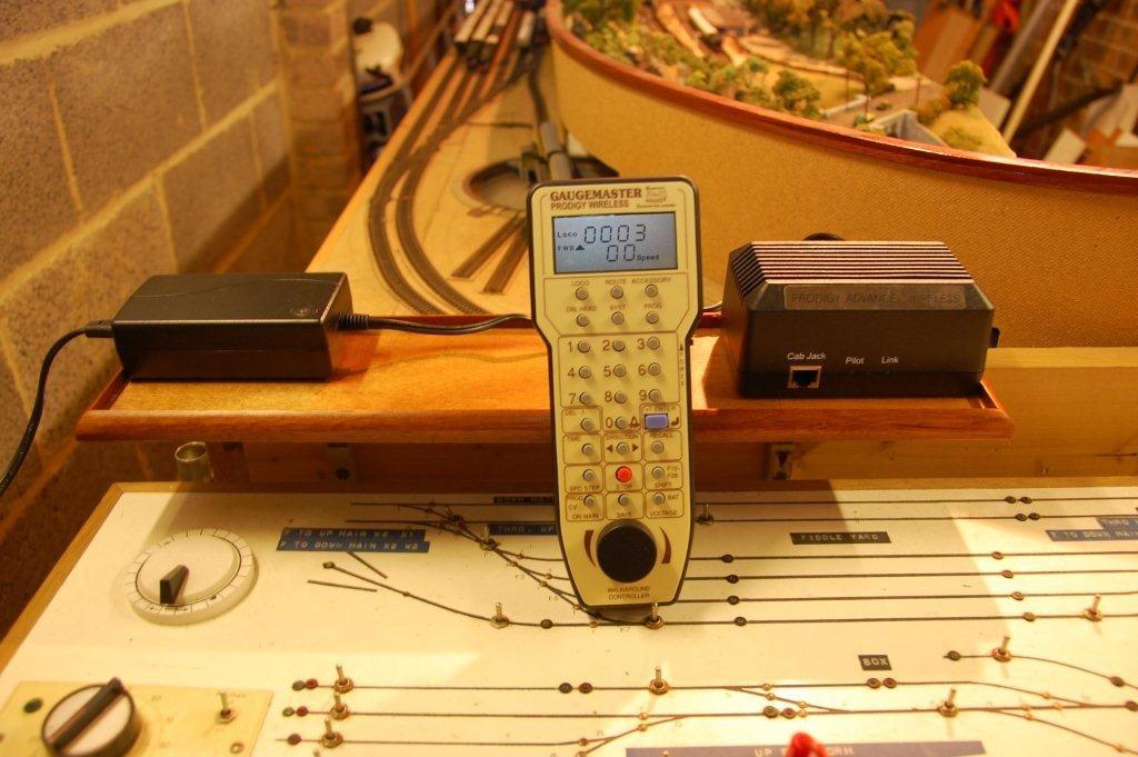
Two little boxes and a wireless hand held controller. If one is so
inclined all of the wiring that is needed for Cab
Control can be ripped out and consigned to the recycling bin. Only two wires are needed to power the track.
15 volts AC. It
is not the normal AC as we know it, it is a higher frequency square
wave
format, not the normal Sine wave. Coded signals are passed down the
track and detected by a chip fitted the locomotive.. each locomotive
chip is programmed with its own address. Only that engine will respond
to any commands given by the hand held controller. The maximum power my
loco's draw is 0.5 Amps and the maximum
power rating of the system is 3.0 Amps, so in theory I can control four
loco's at any one time any where on the track with out overloading the
system and its built in Power off device. This capacity can be increased
by adding power boosters to the track. In addition to this by using
Accessory decoders to the points, routes can be set up with the press of a button.
Scrutiny of my circuit
diagrams shows that I can keep my
original cab control wiring and use both systems at the same time.
All
of my three controllers feed a separate bus and each have a centre off
switch. By switching these off and feeding the other end of the Bus's
with 15V AC and throwing all or any of the section switches in one
direction I can power up any parts of the track that I want to for DCC
control. The chip fitted to the loco is very small
measuring 10.6mm x
8.7mm x 2.8mm. The wheel pickups have to be isolated from the motor
brushes. A lead is taken from each pickup and attached to the relevant
lead on the chip and two leads from the chip go to each of the motor
brushes. As they are soldered connections I use a 15 watt soldering
iron
with a 1.5mm tip. The chip is
programmed with the loco's address from
the hand held controller either on a dedicated test track or on the
main
line. It has three speed settings in 14, 24 or 128 steps, a maximum
speed setting and a minimum voltage required to get the train moving,
variable acceleration and deceleration rates.
It can also produce steam
sound for that loco if you have room to fit a speaker. It will control
the loco head and tail lights of diesel or electric machines. direction
of running can be changed with the press of a button and trains can be
run double headed. With this technology we are in the realm of driving
the train and
not the track and only
two wires to the layout needed.
LOCOMOTIVES
When I first started this project
in 1990 I was ambitious to have one locomotive of each class between
the years 1920 to 1948 pre-nationalisation running on the Great Western
Railway with ths addition of a relic of the Victorian era, a
Dean Steam Rail Motor. This ungainly looking machine when ambling along
at a slow pace and stopping at every station, halt and lamp post has an
appeal which I cannot
explain other than to say that a century ago the pace of travel was
more sedate than todays quest for speed.
The fact that there were 33 classes of loco's running all over the4
system soon brought home the feasibility of my ambition as a non
starter. My layout was far too small to run, let alone house such a large number. To my knowledge all of
the manufacturers of N gauge GWR steam outline ready to run engines
only amounted to about eight. There are of course manufacturers who produce cast white metal body kit which run
on proprietary chassis which are a great help but still a long way
short of 33.
Because of G.J.Churchward's far sightedness of standardising all of the
components of his locomotives, which no other railway did, not only did
he save the company a lot of money in tooling costs he could design and build locomotives of any
required tractive effort to siut all traffic needs simply by using
different combinations of boiler size, piston diameter and length and wheel sizes. Even so, at a board meeting he was
once asked by the Chairman of tha Board, Sir Felix Pole 'why his
engines cost nearly twice as much to build as other railways...', he replied 'because one of my
locomotives can pull two of their "bloody" things backwards'. The only
CME to make a non standard part was Collett who succeeded Churchward and that was because the Southern
Railway brought out their 'Lord Nelson' class whcih they claimed to be
the most powerful 4-6-0 in the world which hither to had been Collett's 'Castle Class'. The GWR board
wanted the title back and instructed Collett to build a more powerful
4-6-0. The outcome was the 'King Class' but he could only do it by reducing the driving
wheels standard 6ft -81/2 to 6ft 6ft 6in diameter to achieve the 40,300
tractive effort to far exceed the 'Lord Nelsons'.
They remained the most powerful 4-6-0 until the demise of steam.
His foresight enabled GWR N gauge enthusiasts to resort to 'kit
bashing' and modifying RTR models into different classes and scratch
build models to run on proprietary chassis.
To date my locomotive stock stands at 21. Five of which have been
chipped for DCC running, the remainder will be in the fullness of time
and money.

